|
Changing the way an object looks
Setting and editing the object style
Each object has a style consisting of a set of attributes. You can set the style to be applied to each new object you create (the default style), and alter the style of existing objects. In both cases, the style is chosen from the Style submenu of the Draw menu.

The style chosen from the Style menu is the default style; all new objects created will be given this style.
To change the style of existing objects, first select the objects you want to change and then change the default style settings.
The Style menu contains the following entries. Each entry has a submenu giving the range of values available.
Line width. You can set the line width to any of a range of predefined values, measured in points (a point is 1/72 inch), or to Thin', which means that the line will always appear in the narrowest width possible. You can use the last position in the menu to type in a value for the thickness if the one you want is not in the menu. Line width applies to paths.
Note that the line width 'Thin' means 'as thin as the output device can manage'. This results in different line thicknesses on different output devices. It is more sensible to use 0.25 points as the default line thickness for a thin line, especially if you will be printing on a typesetter. A 'Thin' line on a 1200dpi imagesetter will be too thin to reproduce subsequently on a litho printer.
Line colour and Fill colour are both set using a colour dialogue box. See the chapter entitled Introducing the Applications Suite for details, but note the following:
- The fill colour applies to the region within the object.
- For a simple line drawing, with no interior, use None as the fill colour.
- Line and fill colours apply to paths.
- Open paths may be filled.
Line pattern is used for dashed and dotted lines. You can set the line pattern to any of a range of patterns, including solid. The pattern applies to paths, rectangles and ellipses.
Dashed and dotted lines can be modified using the Start cap and End cap options.
Join sets how lines are joined together:
 A mitred join brings the outer edges of lines together at a point: A mitred join brings the outer edges of lines together at a point:
 A round join rounds off the point where the lines join: A round join rounds off the point where the lines join:
 A bevelled join cuts off the corner where the lines join: A bevelled join cuts off the corner where the lines join:
The join style only has a significant effect for thick lines.
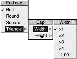
Start cap and End cap determine what the ends of lines look like. Caps apply only to open paths, and their effect is only significant for thick lines. The following are the cap styles:
 Butt caps square off the line at the end point.
 Round caps add a semicircular arc to the end of the line. The diameter of the arc is the same as the width of the line.
 Square caps add a square to the end of the line. The square has half the width of the line.
 Triangle caps add a triangle to the end of the line. The triangle option has its own submenu allowing you to set the height and width of the triangle independently, these values being multiples of the width of the main line. Use this option to create lines with arrowheads.
With Triangle caps you can define the width and height of the Start and End arrowheads proportional to the line width.

In a path, the same style applies to all the line segments.
Note, to generate arrow heads of a reasonable size from start triangle caps and end triangle caps options, you should use values of at least x4 on a 0.5 point line width.
Font name applies to text objects. You can set the font either to the system font, or to an outline font. The list of fonts shows all those that Draw could find when it was loaded. See the RISC OS Six User Guide for more details about how fonts work.
Font size and Font height also apply to text objects. Both values are measured in points (1/72 inch units). You can use the last position in the menu to type in a value if the size or height you want is not already there. Changing the size causes the height to be set to the same value; you can subsequently change the height, leaving the font width set to the size value. System font is 6.4 point wide and 12.8 point high. by default
Text colour is used to set the colour of the text, and the initial text colour of text areas. It is set using a colour dialogue box.
Background is used for setting the intermediate colours used in displaying anti-aliased fonts. You should set this to the same colour as the part of the diagram that the text appears in. For example, if you set the text colour to green and the background to blue, the anti-aliasing pixels will be in a range of shades between green and blue. The background applies to text objects and text areas, and is set using a colour dialogue box.
Winding rule
The winding rule determines whether or not the area enclosed within a path is filled with the selected fill colour. Of course, if the fill has been set as transparent there will be no fill and the winding rule is irrelevant.
The winding rule is normally only significant when several closed paths overlap or enclose each other and all form part of the same object.
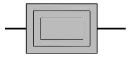
The illustration below shows three concentric squares. These were constructed using the Line and Move tools in the following manner. Begin at the top left (label '1') using the Line tool. (It's best to have Grid Lock turned on while doing this). Create the outer square by drawing from 1 to 2 to 3 to 4. Now, instead of finishing the square by double-clicking, select the Move tool and move the pointer diagonally downwards to a point corresponding to the top left hand corner of the next square. Click SELECT and the point will be created and you will automatically be returned to Line mode. Draw the second square, and then repeat the operation for the third square. This time you can double-click when you get to the top left hand corner again. Because you used the Move tool to move to the next square each time the three concentric squares are one object. Select it and then, from the Style menu choose a suitable fill colour. What you should see when this is applied is shown below on the left.

If you now draw a thick horizontal line and choose Back from the Selection menu so that it is behind the concentric boxes you will see that the middle square has become a 'hole' through which the line beneath is visible. This assumes that the default even-odd winding rule has been applied.
Draw offers a choice of two winding rules. The default even-odd winding rule causes an area to be filled if it is enclosed by an odd number of paths; remember that only paths which make up the object concerned are counted. To determine whether or not any particular area will be filled, place the pointer within that area and then move it slowly until it is right outside the object, counting the number of paths it crosses. If the result is an odd number, the area is filled. If it is even, it is left unfilled and therefore behaves like a hole or window in the object through which other objects behind may be seen.
The alternative non-zero winding rule is used less often. This too counts the number of paths which enclose the area concerned, but the direction of those paths is also taken into account. For each path created clockwise you increase the count by 1 and for each path created anticlockwise you decrease it by 1 (or vice versa). If the number of paths crossed on this basis is 0 (i.e. there were an equal number of clockwise and anticlockwise paths) the area is left unfilled. Otherwise the fill colour is applied.
In the previous illustration the three squares were all formed clockwise. So, if the winding rule is changed to non-zero, all three ellipses are filled and the annular 'hole' disappears. Note that using either winding rule the area contained by the outermost path is always filled. The following illustration is the same as the previous drawing but with the non-zero winding rule applied. All three square sub-paths are filled.

Multiple closed path objects and the winding rules therefore provide a means of introducing holes or windows into shapes.
More formally, the two winding rules are determined as follows:
Even-odd: to determine whether an area of an object is to be filled, imagine a line passing from inside the area to outside the object. Count the number of lines it crosses. If the number is odd, fill the section.
Non-zero: first assign each path a direction, expressed as a number: +1 for one direction and -1 for the other. Then, to see if an area is to be filled, construct an imaginary line from inside the area to outside the figure. Keep a total of the direction values for each line it crosses. If the total is non-zero, fill the section.
Rotating and enlarging objects accurately
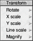
To rotate or enlarge objects by specific amounts firstly select the object(s), then use the Transform submenu, reached from the main menu.

Rotate leads to a submenu into which you can type a rotation angle, measured in degrees. All selected objects are rotated anticlockwise by this angle. Alternatively, you can group the objects and drag on the top righthand ear. You cannot rotate text areas or text lines in System font. If you do want to rotate text in the System font you must first convert the text to a path (see later).
X scale and Y scale lead to submenus into which you can type scale factors. All selected objects are scaled in size by this amount, in the given direction (X = horizontal, Y = vertical). The scaling is relative to the current size. Line widths are not scaled.
Line scale leads to a box in which you can enter a scale factor for the line widths of the selected paths. The scaling is relative to the current size. Lines of width 'Thin' cannot be scaled.
Magnify applies all three scalings - X, Y and Line - to the selected objects (though lines are left unchanged if their width is set to Thin).
Editing existing objects using the Selection menu
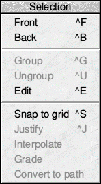
Select mode is used to alter existing objects. You can enter Select mode from the Toolbox (click on the arrow icon), or choose Selection from the Draw menu. The Selection submenu contains a number of operations that you can apply to the currently selected objects:

Front moves the selected objects so that they are at the front of the diagram, obscuring any other objects in the same physical position.
Back moves the selected objects so that they are at the back of the diagram, obscured by any other objects in the same physical position.
Group turns the selected objects into a group object.
Ungroup breaks down a group into the objects that make it up. Ungroup only has an effect when there are groups in the selection.
Edit has two functions. When there is a single path object selected, it provides a means of entering Path Edit mode. The effect is the same as clicking ADJUST on the path object when in Enter mode. When there is a single text line selected, it leads to an edit box in which the text line can be edited.
When a piece of text is selected, an arrow will appear, signalling the presence of the submenu Text. The selected text will appear in the Text box off the submenu. Make your edits to the text, then press Return for the changes to take effect. Existing text cannot be edited directly in a Draw file.
Snap to grid applies only if the grid is locked. It causes the selected objects and each point in them to move to the nearest grid point. In the case of text objects, it is the base line of the characters that will align with the grid.
Justify applies to groups. It leads to a submenu from which you can select how the objects forming the group are arranged within the bounding box of the group object: at the left, centred or at the right horizontally, and at the top, positioned in the middle, or at the bottom vertically.

Convert to path can be applied to a text object to convert it into a normal path. Each letter in the text line is an object, though when you first make the conversion they will be grouped together. Once you have converted a text line to a path, it can be treated like any other path object, and you can also use the options in the Style menu that apply to objects other than text. For example, you can create hollow text by setting a solid line colour and no fill colour.
Once you have converted text to a path it can no longer be 'edited' like a normal text object.

|
![[Select]](../images/ro6doc.gif)
![[Select]](../images/ro6doc.gif)