
|
www.riscos.com Technical Support: |
The RISC OS User Guide has a chapter describing how to use PrintEdit to create new printer definition files, either by starting from scratch or by editing an existing definition. This section contains extra information to help you with more complex tasks.
When using PrintEdit, it is important you understand the Printers back end and the printer dumper used by the printer definition file being edited. The data held in a printer definition file is just that - data. It has no meaning and no pre-ordained use until the printer driver software starts to interpret it. The meaning of any individual data item in the printer definition file is actually imposed by the Printers application and the back end it is using, and by PDriverDP and the printer dumper it is using, rather than by PrintEdit. If PrintEdit lets you type in a certain number or select a certain option, it does not necessarily follow that this will have the desired effect on the software. An example of this is the Dump depth field:
If an existing Printers back end and/or an existing printer dumper will not do what you need, then you will have to write one. To be able to make this decision, you need to find out precisely what the existing back ends and printer dumpers can do by reading this section. It gives a set of PrintEdit example windows, and discusses what can be done with each field. All of the information is available to a Printers back end, but the Printers application only imposes a meaning on some of it. Likewise, all of the data for the current graphics resolution is available to a printer dumper, but PDriverDP only imposes a meaning on a small amount of it.
This information is passed to the dumpers using PDumperReason_SetDriver. This section uses BBC BASIC conventions to show how such data is passed: so R4!(12+40) indicates the word at offset 52 from the location pointed to by R4, whereas R4?(12+0) indicates the byte at offset 12 from the same location. For full details of how the data is passed, you must see PDumperReason_SetDriver (reason code 0).
There have been some changes between RISC OS 3 (version 3.00) and RISC OS 3 (version 3.10) to the graphics sections of printer definition files. Quite a few extra fields have been added, and exactly what all of the fields are used for and when have changed slightly too. Only the RISC OS 3 (version 3.10) behaviour is documented here. Some information on the differences is given in the Printers.Read_Me file. To ensure that your dumper is dealing with format data from RISC OS 3 (version 3.10) or later, check the version number passed to PDumperReason_SetDriver, which should be 3 or greater.
The most common use of PrintEdit is for dealing with Epson/IBM compatible printers. In each of the sections below we will use them as the core example and for discussing general points. Any points specific to other classes of printers appear at the end of each section.
The appearance of the Printer definition editor window when the Epson EX-800 printer definition file is loaded is as follows:
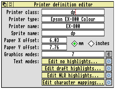
The Printer class represents a type of printer; it determines which back end Printers uses for the printer. For Epson and IBM-compatible printers this field should be set to dp, so that the !Printers.dp back end is used.
Printer type is the full name of the printer. It us used to differentiate between printer definitions. If you try to overload a printer definition with one having the same printer type, the old data is retained. This avoids any delays that might occur if the user tries to load the same file twice.
It follows that if you make minor alterations to a definition and wish to load it in place of or beside the original, you must change the printer type.
Printer name is the name you want to appear underneath the printer on the icon bar. The name can be up to 10 characters long.
Sprite name determines the sprites to be used by the Printers application as the printer icon on the icon bar. When the printer is the default, Printers uses the named sprite, which should be cream. When the printer is not the default, Printers precedes the sprite name with 's_' and instead uses that sprite - which should be grey. See !Printers.dp.Resources.!Sprites for example sprites.
For Epson and IBM-compatible printers this field should be set to dp, which makes the Printers application use the two sprites dp and s_dp.
The paper offsets represent the top (Y) and left (X) sections of the paper on which the printer cannot physically print. The Paper Y offset is the amount of cut sheet paper which has already gone past the print head before it can print anything; this differs for different printer models. Similarly the Paper X offset is the small section at the left hand edge on which the head cannot print, although why this is so is not always obvious. Together the paper offsets define the logical (0,0) origin on the physical paper. The Printers.Read_Me file contains details on using the Printers.Top_Left file to set the offsets for Epson and IBM compatible dot matrix printers.
Normally the paper offsets will be set correctly for the printer being used. However, if necessary you can change the paper offsets away from their true values, probably by using negative numbers. This allows you to move the image around on the paper if you need to do so and there is no facility for this in the application doing the printing. Unfortunately it is not easy to do the same sort of trick with PostScript printers, so think about whether you ever need to use PostScript before resorting to this trick. Do not try to use the Graphics margins in Printers to move the image, as that is not their function.
PrintEdit actually holds the paper offsets in each of the graphics resolution data blocks in units of pixels at that printer resolution, converting them from the units in which they were specified as it does so. These values are passed to the dumper by PDumperReason_SetDriver in words R4!(12+40) and R4!(12+44); it is then the responsibility of the printer dumper to act on this information if it wishes to. The Acorn printer dumpers all subtract the paper offsets from the top and left margins passed to them by PDriverDP (also in units of pixels), since the section of the margins which is within the paper offsets has already been skipped implicitly by the printer mechanism.
Graphics modes shows the number of graphics modes that have been defined for your printer. For details of editing their settings, see the sections starting on Graphics mode: Dump information.
Text modes defines the type of text modes your printer can use. For Epson and IBM-compatible printers there are four categories available.
The appearance of the Printer definition editor window with the Printers.Integrex.ColJet132 file loaded is:
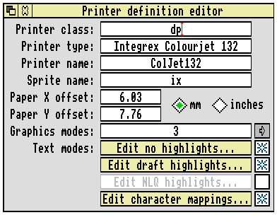
The Integrex back end is combined with the generic dot-matrix back end. Consequently the Printer class remains as dp. However, the Sprite name is ix, so that the icon on the icon bar is the same under RISC OS 3 as it was for !PrinterIX on RISC OS 2.
The appearance of the Printer definition editor window with the Printers.Apple.ImgWriteII file loaded is:
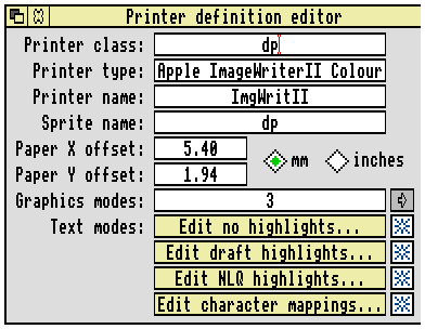
The Image Writer back end is combined with the generic dot-matrix back end. Consequently the Printer class remains as dp.
The appearance of the Printer definition editor window with the Printers.HP.DeskJet+ file loaded is:
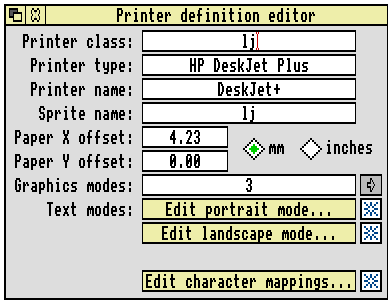
The differing text mode titles (Edit portrait mode and Edit landscape mode rather than 'Edit no highlights', 'Edit draft highlights' and 'Edit NLQ highlights') are set up by PrintEdit when the Printer class is lj. The information is still stored in exactly the same way as for Epson and IBM-compatibles.
The Dump information in the Graphics mode window for the Epson.EX-800 file at a resolution of 240 by 216 dpi is shown below:
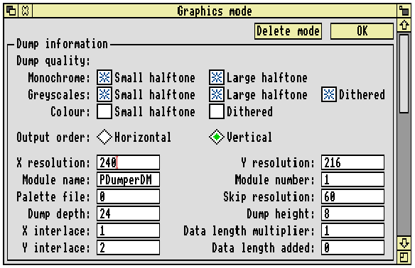
The meaning of much of this information is imposed by PDriverDP, and to a lesser extent the back end. The items which are not used by PDriverDP or the Printers application and are passed to a dumper using PDumperReason_SetDriver are:
It is the dumper that gives meaning to the information these fields hold. You can therefore use them to pass any numeric information to a new dumper, irrespective of their title in this PrintEdit window.
The Dump quality boxes should normally all be selected, as most of the software supports these features on most printers. You should not select the colour options for dot matrix printers that do not support colour. It is also good practice not to enable the colour options for resolutions which use horizontal or vertical interlace. The Dump quality boxes which you select will be made available by the relevant back end in the Quality menu of the printer configuration window.
Output order is specific to dp class printers, and is only acted on by PDumperDM. It selects between the parts of the dumper that are for Epson/IBM compatible printers (output order is Vertical), or the parts that are for Integrex ColourJet 132 compatible printers (output order is Horizontal).
Note that when Horizontal order has been selected many of the other Dump information and Dump strings settings either become irrelevant, or must be set to certain values. See the chapter entitled Integrex printers.
X (horizontal) and Y resolution (vertical) define the graphics resolution in dots per inch. These should be given in your printer manual, but may be in different units. The printer manual will usually quote resolutions before vertical interlacing has been applied (see later), so in this case the manual would quote 240 by 72 dpi, rather than 240 by 216 dpi (since 216/3 = 72). The manual is also likely to give dots per line rather than dots per inch for the horizontal resolution; for example, 960 dots per line on 8 inch paper is 120 dpi horizontal resolution. The vertical resolution is often omitted altogether, in which case it is likely to be 72 dpi for 9 pin printers, 180 dpi for 24 pin printers doing 24 pin graphics, 60 dpi for Epson 24 pin printers doing emulated 8 pin graphics, and 72 dpi for IBM 24 pin printers doing emulated 8 pin graphics.
Module name and Module number define the PDumper module used for the printer. For more information see the chapter entitled Printer dumper numbers and names.
Palette file defines the palette file name, which is currently always 0. This corresponds to the file !Printers.Palettes.0 (or rather Printers:Palettes.0). This pathname is constructed by the back end from the filename given in the printer definition file. It is passed to the dumpers by PDumperReason_SetDriver in the string pointed to by R3. The Acorn printer dumpers all pass this pathname to the PDumperSupport module, which loads and uses this file for colour matching and halftoning data.
Skip resolution defines the leading zero skip resolution in dots per inch. This is almost always 60 for Epson printers (the resolution of 27, '$') and 120 for IBM printers (the resolution of 27, 'd').
The zero skip resolution as passed to the dumpers needs some explanation. It is passed in a form that is easier for the dumper code to use, as a multiplier (R4!(12+24)) and a divider (R4!(12+28)). There is also a specified number of leading zeros you should leave to allow the print head time to accelerate (R4?(12+23)). Finally you should include the left margin in output pixels (R4!268), by adding it to the number of actual zero printer pixels at the start of your output data.
To convert from a number of zero pixels at the output horizontal resolution to a number of zero skip pixels, use the following formula:
The number of actual zero data pixels which should still be output as print data is a combination of the remainder from this and the run_up itself, given by:
You can probably perform the DIV and the MOD of ((output_zeros + left_margin - run_up) × multiplier) as a single operation if you are writing your dumper in assembler. If (output_zeros + left_margin - run_up) is negative, then you should do no leading zero skipping, and the actual number of print data zeros to output should be:
Remember that if you need to use paper offsets in your dumper (which depends on the type of printers it is for), before using the left_margin in the above calculations you must subtract the paper X offset from it:
If this gives a negative left margin, then set it to zero. The divider and/or multiplier are optimised down to 1 if possible by PrintEdit (eg. 180 dpi output, 60 dpi skip gives multiplier of 1 and divider of 3), so your DIV and MOD code should be optimised for small numbers (1 in particular), or should treat 1 as a special case if not optimised.
Dump depth (R4?0) is the number of pins on the print head (ie Dump height) multiplied by the number of vertical interlace passes (ie Y interlace + 1); so for the EX-800 at 240 by 216 dpi, the Dump depth of 24 is obtained from 8 pins and a Y interlace of 2, giving 8 × (2 + 1) = 24. PDumperDM (with vertical output) requires the Dump depth to be a multiple of 8.
Dump height (R4?(12+2)) is the number of pins used for graphics printing on the print head; for example it is 8 on 9 pin printers. PDumperDM (with vertical output) requires the Dump height to be a multiple of 8.
X interlace (R4?2) is the number of horizontal interlace passes of the print head (starting from pass 0). For example at 240 dpi horizontal resolution most printers cannot print adjacent dots, so two passes (X interlace of 1) are required, with alternate dots set to zero:
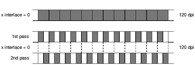 X interlacing with two horizontal passes
Note that this diagram shows a simplified view of the situation. In particular, it shows the dots made by the pins as being half as wide when performing interlacing (240 dpi). This is not the case, since the pins are obviously fixed in size, and the dots are just as wide as for 120 dpi. Each dot printed actually covers the entire of the blank (zero) dot to the right of it, with the obvious effect that dots from the two interlace passes actually overlap. This does not really affect the resolution of the printout, the actual effect being that the centre of a dot is 1/480" further right than the code thinks it is, and hence so is the entire printout. It does however make the printout darker.
Y interlace (R4?1) is the number of vertical interlace passes of the print head (starting from pass 0). For example a 9 pin printer doing 8 pin graphics is fundamentally doing 72 dpi vertical resolution, because that is how far apart the pins are. But by feeding the paper by a fraction of the pin separation and making another pass of the head, greater resolution can be achieved at the cost of speed:
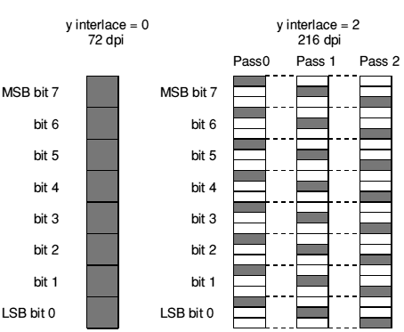 Y interlacing with two horizontal passes
After pass 0 the paper is fed by 1/216", and again after pass 1. After pass 2 the paper is fed by 22/216", so the total feed is a full head width for an eight pin head, since 24/216" = 8/72".
Just as for horizontal interlacing, this diagram shows a simplified view of the situation. In particular, it shows the dots made by the pins as being one third height when performing interlacing (216 dpi). This is not the case, since the pins are obviously fixed in size, and the dots are just as tall as for 72 dpi. Each dot printed actually covers both of the blank dots below it, with the obvious effect that dots from the three interlace passes actually overlap. This does not really affect the resolution of the printout, the actual effect being that the centre of a dot is 1/72" further down than the code thinks it is, and hence so is the entire printout. It does make the printout darker however.
The Data length multiplier (R4?(12+0)) and Data length added (R4?(12+1)) are used to convert the number of columns in a row of graphics out to the data length that must be passed to the printer.
where low byte × 256 + high byte = size.
Both schemes are sensible; they are just different ways of counting how much data there is in the graphics line.
For colour ribbon printing, the contents of a '(dump depth)' are different. This is described below after the relevant PrintEdit fields have been described.
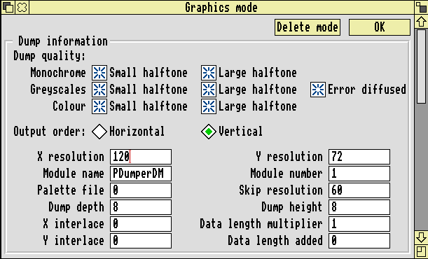
For colour printing, consider the Epson EX-800 at 120 by 72 dpi. The Dump information (which is fairly obvious and therefore needs no description) is as follows:
The Dump information at 160 by 126 dpi for an Integrex printer is:

The Integrex dumper is combined in PDumperDM with the generic dot-matrix dumper. Consequently the Module name and Module number remain as PDumperDM and 1 respectively. However, as noted above, the Output order must be Horizontal for Integrex printers to enable the correct parts of PDumperDM. The dumper also relies on the Dump depth and Dump height both being set to 1.
The Dump information at 160 by 144 dpi for an ImageWriter printer is:
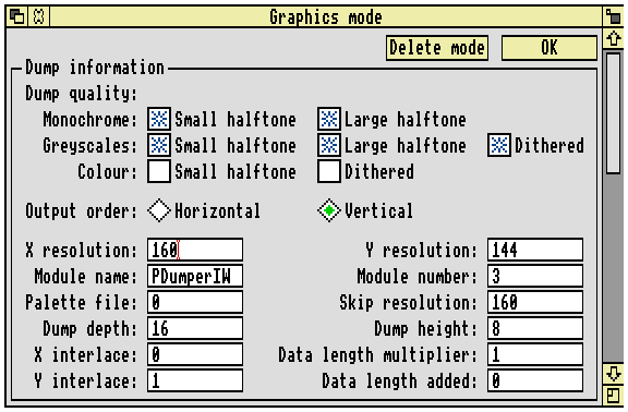
For an ImageWriter, the Module name and Module number are PDumperIW and 3 respectively; although it uses the same back end as generic dot-matrix printers, it requires its own dumper. The reasons for this are outlined on ImageWriter printer.
ImageWriter printers need no extra data after the length and so have a Data length multiplier of 1 and a Data length added of 0. The Skip resolution is usually the same as the X resolution.
The Dump information for the HP DeskJet+ at 300 by 300 dpi is:
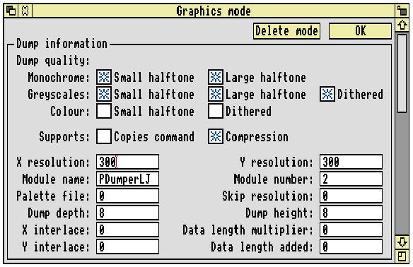
Most of these fields must have these values, otherwise PDumperLJ will not work. The current version of PDumperLJ has no support for colour printing, hence you must not select the colour options.
The Printer class of lj (set in the main window) causes PrintEdit to show the Supports options, rather than the Output order shown by dp class printers:
These flags are passed to PDumperReason_SetDriver in R5; if bit 0 (LSB) is set, then Copies command was selected; if bit 1 is set, then Compression was selected.
There is nothing else you can usefully do with this window when the printer definition file is used in conjunction with the RISC OS 3 (version 3.10) PDumperLJ.
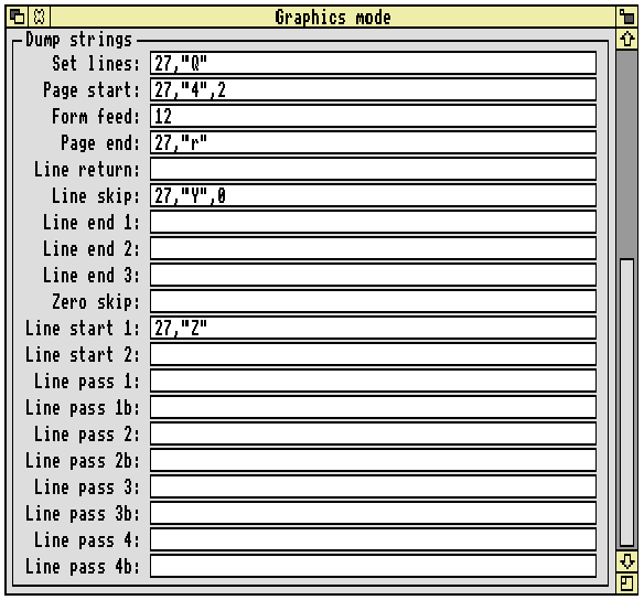
The second part of the Graphics mode window gives the Dump strings:
These are the codes sent to the printer to tell it to perform certain actions. Only the dumper uses these strings, and hence a new dumper can use any of these strings to hold anything. The PrintEdit window reflects the usage that PDumperDM and PDumperIW make of these strings.
Set lines (R4?(12+21)) is the string to define the number of lines per page. The number of lines (R4?(12+22)) is sent as a single byte after the set lines string (eg. 27, 'C', 70 when using A4 paper, which is 70 lines long). The length used is the height in lines from the Text margins section of the Printers application's Paper sizes window, and is put into the graphics data block by the !Printers.dp back end.
This sequence is not sent if the number of lines is set to 0, since on Epson compatible printers 27, 'C', 0 actually means that the next byte sent after the 0 is the length of the paper in inches.
This sequence solves the problem with the RISC OS 2 and RISC OS 3 (version 3.00) printer drivers whereby the printer's DIP switches had to be set correctly for the paper size you were using. Normally the switches allow only 11" or 12", and since A4 paper is 11.64" long, form feeds between pages on A4 fanfold paper (or any other non standard paper size) fed the paper to the wrong place.
Page start (R4?(12+3)) is the string sent at the start of a page, after the set lines sequence. It is generally used to switch emulations, or to set the line feed pitch to zero. The reason for setting the line feed pitch to zero is to avoid problems with auto line feed on carriage return. With the line feed pitch set to zero, it really doesn't matter if an auto line feed happens since it will do nothing anyway. Thus graphics printing does not care which way the auto line feed DIP switch is set on the printer, due to the careful construction of the printer definition files.
Setting the line feed pitch to zero (or to the head height of 8/72", or indeed to any other number) relies on such a change not affecting the page length previously set up by the Set lines sequence. (Similarly you must not reset the printer in the Page start sequence, or the page length setting will be reset to the default.) Epson and IBM compatible printers convert the page length to an absolute size internally, so they are not affected by a subsequent change in line pitch.
If your printer is affected by a subsequent change in line pitch, then you must not change the pitch in the Page start string. You could change it at the start of the Set lines string and have a blank Page start string, but you would then need the number of lines in the Printers application's text margins to be correct for both text and graphics spacing, which are seldom the same. Possible work rounds are:
For example, text is usually 6 lines per inch, whereas 8 pin graphics is usually 9 lines per inch (72 dpi pitch / 8 dots per line), so the number of graphics lines per page would be 3/2 times the number of text lines per page.
Similarly, 24 pin graphics are usually 71/2 lines per inch (180 dpi / 24 pins), leading to a conversion factor of 5/4
Doubtless there are other solutions to this problem.
Form feed (R4?(12+36)) is the string sent to the printer to tell it to form feed the paper after each page has been printed. This string is not sent by PDumperDM when the Roll paper feed setting is selected in the Printers application.
To aid recovery from aborted jobs, we recommend that form feed strings always contain a form feed, page end strings a full printer reset, and end of text job strings both a form feed and full printer reset.
Page end (R4?(12+4)) is the string sent at the end of each page, after the form feed string (if present). It is usual to reset the printer (eg 27, '@' for Epson printers) in this string, so that if this page is the last one, the printer is reset to a known state set by the user on the DIP switches. This string must also set the printer 'top of form' (TOF), or the Roll paper feed setting in the Printers application may not work correctly, because the printer may do a form feed of its own when it thinks it has printed a full page. On Epson compatible printers, 27, '@' resets TOF at the same time as resetting the printer to the default settings, but on other printers (eg. IBM compatibles) a separate string is needed to reset TOF.
Line return (R4?(12+5)) moves the print head to the beginning of the current line. Usually this will be a carriage return. This string is used when performing horizontal interlacing and multi pass colour ribbon printing.
Line skip (R4?(12+6)) moves the print head to the beginning of the next line, and is used for skipping entirely blank lines. For example on the EX-800 at 240 by 216 dpi this string feeds the paper by 24/216" and performs a carriage return.
Line end 1 (R4?(12+7)) to Line end 3 (R4?(12+9)) are the strings sent at the end of each vertical interlace pass. For example on the EX-800 at 240 by 216 dpi, after the first vertical interlace pass Line end 1 is sent to the printer, which feeds the paper by 1/216" and performs a carriage return. Line end 2 does the same after the second vertical interlace pass, and then after the final vertical interlace pass Line end 3 feeds the paper by 22/216" (27, 'J', 22) and performs a carriage return.
Zero skip (R4?(12+10)) is issued to skip leading zeros on graphics data lines, hence optimising out the white section at the left hand edge of the paper. The string is followed by a two byte number (low byte, high byte) of dots (columns) to skip at the skip resolution; for example 27, '$', 1, 97. A small amount of leading zeros (1/6" worth) is left in the graphics data. This is necessary to allow the print head to accelerate up to speed before the pins print anything.
Line start 1 (string offset R4?(12+11)) is the string sent at the beginning of a graphics line. This is followed by the length of the line, reduced to the minimum necessary to represent the data that is to be printed (to avoid sending unnecessary trailing zeros), and with the Data length multiplier and Data length added applied. The length is then followed by Line start 2 (R4?(12+12)).
Therefore, for an Epson Line start 1 is typically 27, '*', graphics mode, and Line start 2 is unused; whereas for an IBM Line start 1 is typically 27, '[', 'g', and Line start 2 is graphics mode. For more details, see the description of the Data length multiplier and adder.
If you want to use PrintEdit to look at some printer definition files with Line start 2 sequences present, the IBM Pro-X24E and the Canon BubbleJet are good examples.
The sequence of data output for a black and white page to the EX-800 at 240 by 216 dpi is shown below. This is for PDumperDM with the Output order set to Vertical.
PDumperDM has a system variable associated with it named PDumperDM$Extra. This is currently unused, but is included in the sequence for the sake of completeness.
The notation used is as follows:
The sequence for a page is:
| (PDumperDM$Extra) | (currently unused) | |
| <Set lines>[line count]<Page start> | ||
| <Line skip> | repeated until last line at top of page that does not print output | |
| (dump depth) | repeated until last line that prints output to page (ie is non-zero) | |
| <Form feed><Page end> | ||
Each '(dump depth)' is a complete set of horizontal and vertical interlace passes, and each one occupies the same amount of paper as a '<Line skip>'. The contents of a '(dump depth)' for our example (2 horizontal interlace passes for each of 3 vertical interlace passes) are:
<Zero skip>{length}<Line start 1>{length}<Line start 2>
(graphics data for 0th horizontal pass)<Line return>
<Zero skip>{length}<Line start 1>{length}<Line start 2>
(graphics data for 1st horizontal pass)<Line end 1>
<Zero skip>{length}<Line start 1>{length}<Line start 2>
(graphics data for 0th horizontal pass)<Line return>
<Zero skip>{length}<Line start 1>{length}<Line start 2>
(graphics data for 1st horizontal pass)<Line end 2>
<Zero skip>{length}<Line start 1>{length}<Line start 2>
(graphics data for 0th horizontal pass)<Line return>
<Zero skip>{length}<Line start 1>{length}<Line start 2>
(graphics data for 1st horizontal pass)<Line end 3>
To achieve horizontal interlacing the graphics data for each '0th horizontal pass' goes byte, 0, byte, 0, byte, 0 etc, whereas the graphics data for each '1st horizontal pass' goes 0, byte, 0, byte, 0, byte etc.
Any individual vertical interlace pass which is entirely blank (ie consists of zeros) will not be output at all. However, if any one of a set of horizontal interlace passes is not blank (ie a pair of passes in the above example), all those horizontal passes will still be output. Leading and trailing zero suppression (using Zero skip and data length reduction as mentioned above) are also performed at this level.
The Dump strings for colour printing are:
When printing at 120 by 72 dpi in monochrome or grey scale, the strings documented earlier are used. When printing in colour, Line start 1 and Line start 2 are not used. The eight line pass strings are used instead.
Line pass 1 (R4?(12+13)) and Line pass 1b (R4?(12+14)) are the equivalents of Line start 1 and Line start 2 for the yellow ribbon pass. The two strings are usually the same as the Line start strings, with the addition that Line pass 1 will select yellow before starting the graphics data.
Similarly, Line pass 2 (R4?(12+15)) and Line pass 2b (R4?(12+16)) are used for the magenta ribbon pass; Line pass 3 (R4?(12+17)) and Line pass 3b (R4?(12+18)) are used for the cyan ribbon pass; and Line pass 4 (R4?(12+19)) and Line pass 4b (R4?(12+20)) are used for the black ('Key black' in CMYK parlance) ribbon pass.
The four colour passes are performed one after the other - yellow, then magenta, then cyan, then black - with a Line return between each pass. If you were to attempt to use interlacing and colour (which is not recommended), you would find that horizontal interlacing occurs before the 4 colour process, and vertical interlacing occurs afterwards over the entire 4 colours. You should use horizontal interlacing in preference to vertical interlacing since horizontal will not contaminate the light ribbon colours, whereas vertical interlacing would by printing the lighter colours on top of the darker ones already present on the paper from the previous interlace pass. For an ink jet this is irrelevant, but interlacing is also usually irrelevant.
Thus a '(dump depth)' for a colour printout (with no interlacing) will be:
<Zero skip>{length}<Line pass 1>{length}<Line pass 1b>
(graphics data for yellow pass)<Line return>
<Zero skip>{length}<Line pass 2>{length}<Line pass 2b>
(graphics data for magenta pass)<Line return>
<Zero skip>{length}<Line pass 3>{length}<Line pass 3b>
(graphics data for cyan pass)<Line return>
<Zero skip>{length}<Line pass 4>{length}<Line pass 4b>
(graphics data for black pass)<Line end 1>
At 240 by 144 dpi (2 horizontal interlace passes for each of 2 vertical interlace passes) a '(dump depth)' would be:
<Zero skip>{length}<Line pass 1>{length}<Line pass 1b>
(graphics data for 0th horizontal yellow pass)<Line return>
<Zero skip>{length}<Line pass 1>{length}<Line pass 1b>
(graphics data for 1st horizontal yellow pass)<Line return>
<Zero skip>{length}<Line pass 2>{length}<Line pass 2b>
(graphics data for 0th horizontal magenta pass)<Line return>
<Zero skip>{length}<Line pass 2>{length}<Line pass 2b>
(graphics data for 1st horizontal magenta pass)<Line return>
<Zero skip>{length}<Line pass 3>{length}<Line pass 3b>
(graphics data for 0th horizontal cyan pass)<Line return>
<Zero skip>{length}<Line pass 3>{length}<Line pass 3b>
(graphics data for 1st horizontal cyan pass)<Line return>
<Zero skip>{length}<Line pass 4>{length}<Line pass 4b>
(graphics data for 0th horizontal black pass)<Line return>
<Zero skip>{length}<Line pass 4>{length}<Line pass 4b>
(graphics data for 1st horizontal black pass)<Line end 1>
<Zero skip>{length}<Line pass 1>{length}<Line pass 1b>
(graphics data for 0th horizontal yellow pass)<Line return>
<Zero skip>{length}<Line pass 1>{length}<Line pass 1b>
(graphics data for 1st horizontal yellow pass)<Line return>
<Zero skip>{length}<Line pass 2>{length}<Line pass 2b>
(graphics data for 0th horizontal magenta pass)<Line return>
<Zero skip>{length}<Line pass 2>{length}<Line pass 2b>
(graphics data for 1st horizontal magenta pass)<Line return>
<Zero skip>{length}<Line pass 3>{length}<Line pass 3b>
(graphics data for 0th horizontal cyan pass)<Line return>
<Zero skip>{length}<Line pass 3>{length}<Line pass 3b>
(graphics data for 1st horizontal cyan pass)<Line return>
<Zero skip>{length}<Line pass 4>{length}<Line pass 4b>
(graphics data for 0th horizontal black pass)<Line return>
<Zero skip>{length}<Line pass 4>{length}<Line pass 4b>
(graphics data for 1st horizontal black pass)<Line end 2>
where <Line end 1> is 27, 'J', 1, 13 and <Line end 2> is 27, 'J', 23, 13 for the Epson EX-800.
To achieve horizontal interlacing the graphics data for each '0th horizontal pass' goes byte, 0, byte, 0, byte, 0 etc, whereas the graphics data for each '1st horizontal pass' goes 0, byte, 0, byte, 0, byte etc.
Any individual colour pass (Yellow, Cyan, Magenta or Key black) or vertical interlace pass which is entirely blank (ie consists of zeros) will not be output at all. However, if any one of a set of horizontal interlace passes is not blank (ie a pair of passes in the above example), all those horizontal passes will still be output. Leading and trailing zero suppression (using Zero skip and data length reduction as mentioned above) are also performed at this level.
The two most likely scenarios are some of the colour passes being absent (particularly yellow, magenta and cyan being absent with just black present), and an entire '(dump depth)' being absent. Below is an example dump depth at 240 by 144 dpi where only yellow and cyan are in use:
<Zero skip>{length}<Line pass 1>{length}<Line pass 1b>
(graphics data for 0th horizontal yellow pass)<Line return>
<Zero skip>{length}<Line pass 1>{length}<Line pass 1b>
(graphics data for 1st horizontal yellow pass)<Line return>
<Zero skip>{length}<Line pass 3>{length}<Line pass 3b>
(graphics data for 0th horizontal cyan pass)<Line return>
<Zero skip>{length}<Line pass 3>{length}<Line pass 3b>
(graphics data for 1st horizontal cyan pass)<Line end 1>
<Zero skip>{length}<Line pass 1>{length}<Line pass 1b>
(graphics data for 0th horizontal yellow pass)<Line return>
<Zero skip>{length}<Line pass 1>{length}<Line pass 1b>
(graphics data for 1st horizontal yellow pass)<Line return>
<Zero skip>{length}<Line pass 3>{length}<Line pass 3b>
(graphics data for 0th horizontal cyan pass)<Line return>
<Zero skip>{length}<Line pass 3>{length}<Line pass 3b>
(graphics data for 1st horizontal cyan pass)<Line end 2>
You might like to think of printing in black only as a special case of coloured printing, the only difference being that it uses the Line start strings rather than the Line pass strings.
Below is an example entirely blank '(dump depth)' at 240 by 144 dpi:
<Line end 1>
<Line end 2>
The Line end sequences are the minimum that it is reasonable to optimise the output down to, because they contain the paper movement commands. It would be possible to spot an entirely empty '(dump depth)' and replace the sequence of Line end strings with a single Line skip, but in practice it saves too little to be worth the extra code complexity.
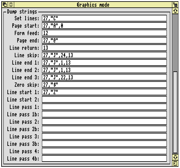
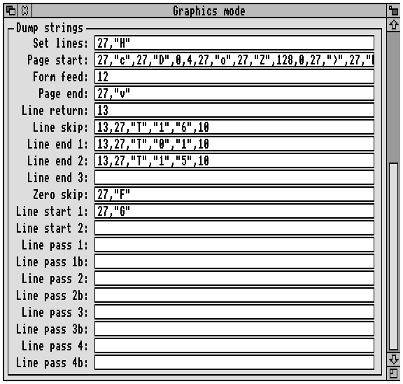
The Dump strings for an Integrex printer at 160 by 126 dpi are:
Only the strings present above will be acted on by PDumperDM, which ignores any of the rest that you might fill in. The strings present have the same broad meaning as they did for Epson and IBM printers, and are even output in the same order. The subtle detail is slightly different though.
Set lines, Form feed and Page end are exactly as for Epson and IBM compatible printers, as is the Page start string, save that it is used to specify the vertical resolution.
Line skip is strictly speaking the same, but since it skips a '(dump depth)', and the Dump depth is always set to 1 for Integrex printers, the actual amount of paper skipped is a lot less: in fact a single printer pixel row, since the Integrex is effectively a one pin printer.
Line start 1 is also the same in a strict sense, since it is output before the data. The main data sequence for Integrex printers is the same as for other printers:
| (PDumperDM$Extra) | (currently unused)
| <Set lines>[line count]<Page start>
| <Line skip>
| repeated until last line at top of page that does not print output
| (dump depth)
| repeated until last line that prints output to page (ie is non-zero)
| <Form feed><Page end>
| | ||
but each '(dump depth)' is substantially different, consisting of a single horizontal printer pixel row:
<Line start 1>[n](n bytes red data)(n bytes green data)(n bytes blue data)
The printer merges the red, green and blue data to form a single raster line of CMYK dots, which it then prints. The MSB of a single byte of raster data is printed first (ie on the left).
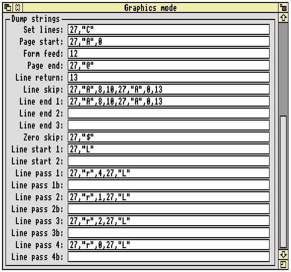
The Dump strings at 160 by 144 dpi for an ImageWriter printer are:
All of these are used in a similar way as for Epson and IBM printers, as is the PDumperIW$Extra system variable (again, currently unused). PDumperIW also follows the same sequence of data output as PDumperDM (see Sequence of data output), However, there are differences in the format the data in each '(dump depth)' takes - which is why the ImageWriter requires its own dumper. In particular:
For example:
In obtaining this number, PDumperIW assumes that there are 6 lines per inch, so the conversion factor is 144/6 = 24. A4 paper is 70 lines long, so 70 × 24 = 1680.
For HP LaserJet compatible printers, the options for graphics printing configuration are very limited. The dump strings are unused, the control strings being set in the PDumperLJ module instead. With hindsight we recommend that - if at all possible - you do not follow this approach when writing a dumper. Use the dump strings, even if the contents are used for something totally different to what the PrintEdit names imply they should be for. The flexibility gained by doing this is worth the potential confusion.
Because PDumperLJ has so little flexibility and can only drive standard LaserJet and DeskJet compatible printers, there is no point in describing the data sequence. Either your printer will work with one of the four supplied printer definition files, or it will not work at all and using PrintEdit will not help. See also the file Printers.HP.Read_Me.
The PDumperLJ$Extra system variable is set by the !Printers.lj back end and is output by PDumperLJ. It contains the control sequence to select either manual feed or auto feed, and the control sequence to select the correct paper size. These strings are read from the !Printers.lj.Resources.Messages file by the !Printers.lj back end, with the following tokens:
The strings after each token may safely be changed if your printer needs a different control sequence, and you may add extra PT_ tokens for any additional paper sizes you may need. For example, if you define a paper size of A3 (Generic LJ) and the control sequence to select A3 paper is:
|[&199A
then you would need to add the line:
PT_A3:|[&199A
to the file.
The string for PT_A4 is used if there is no token for the paper size selected in the Printers application's printer configuration window.
Text printing is done by the Printers back end in use (dp, lj or ps) and as such has nothing to do with dumpers. However, there are some points worth mentioning since you will need some text printing definitions to go with a new dumper. No highlights, Draft highlights and NLQ highlights are very similar, so only one will be described in detail. Below is the Text - NLQ highlights window for a dp class printer: the Epson.EX-800 file:
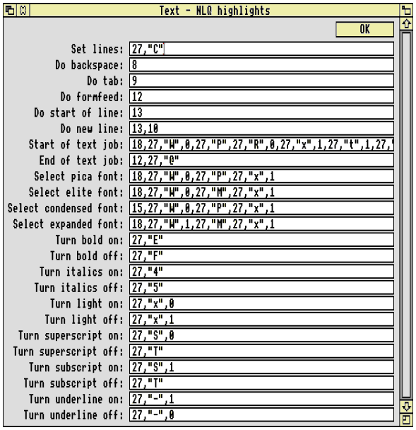
Set lines operates in the same way as for graphics printing; it is followed by a byte specifying the length, and is not sent if the length is zero. Unlike graphics printing, the Set lines sequence is sent after the Start of text job sequence.
Do backspace, Do tab and Do formfeed are obvious.
Only one of Do start of line and Do new line is used. If Print linefeeds is selected in the Printers application's printer configuration window, then Do new line is sent at the end of each text line. If Print linefeeds is not selected, then Do start of line is sent instead.
Start of text job is sent at the very beginning of the text job. You may assume that the printer has been reset at the end of the preceding text or graphics job, but you should not assume the DIP switch settings. The contents of the Select pica font string should always be included in the Start of text job string, because the !Printers.dp back end assumes that the printer is set up for pica at the start of the job. On a printer that can do NLQ printing, you should enable or disable NLQ mode appropriately for all three sets of highlights. The full string does not fit into the PrintEdit icon as shown above. It is:
18, 27, 'W', 0, 27, 'P', 27, 'R', 0, 27, 'x', 1, 27, 't', 1, 27, '6'
Splitting this up into components:
Much of this is needed for the character mappings supplied. As you can see, the Start of text job sequence has to get lots of things set up correctly to simplify everything else.
End of text job usually just does a form feed and resets the printer. It is standard Acorn practice to reset dp printers at the end of jobs (text and graphics) but not at the start. One of the reasons behind not doing it at the start of the job is that it lets the user use some of the printer's front panel controls to select various options if he wants, which with luck will remain in effect throughout the print job (although they will probably be turned off by the reset at the end). If the reset were at the start of print jobs, this would not be possible.
Select pica font selects a 10 cpi (characters per inch) printer font. This is the default, and it is assumed that all printers can support it. All font selection strings should ensure they correctly disable anything that any of the other font selection strings enable.
Select elite font selects a 12 cpi printer font. If there is no 12 cpi font then you should select the closest, which will usually be 10 cpi.
Select condensed font selects a 17 cpi printer font, which nearly all printers support. Again you should select the closest size if 17 cpi is not available.
Select expanded font selects a 6 cpi printer font. This is usually achieved by selecting 12 cpi, and turning double width printing on with 27, 'W', 1 (which is why all the other font selection strings turn double width off). If there is no 6 (12) cpi font then you should select the closest size. This usually means selecting 10 cpi and double width printing to give 5 cpi.
Turn bold on/off, Turn italics on/off, Turn superscript on/off, Turn subscript on/off and Turn underline on/off are obvious.
Turn light on and Turn light off are difficult to support as dot matrix printers generally have no concept of light printing. In NLQ highlights, it is Acorn practice to turn NLQ mode off for light printing, and turn it back on again when normal printing resumes. There could be a conflict if a font selection string is issued half way through the light printing, as the font selection strings usually enable NLQ. This is a specific instance of a general problem with 1st Word Plus file fancy text printing, which is that different styles and effects should be mixed sparingly. For example many printers cannot underline superscripts and subscripts, or print them in bold.
Text modes on Integrex printers work in the same way as for Epson/IBM compatible printers.
Text modes on the ImageWriter printer works in the same way as for Epson/IBM compatible printers, save that the length is sent as a four digit decimal string using the same units and conversion factor as for graphics printing. This is done by the !Printers.dp back end if the name of the dumper to use is PDumperIW, and was done to avoid having a new printer class and back-end just to handle this one difference in text printing.
The text highlights and character mappings in all the lj printer class files supplied with RISC OS 3 (version 3.10) are identical. This fortunate state of affairs is because when talking to LaserJet compatible printers, you can tell the printer to do something and if it can't it is up to the printer itself to decide what compromise to make. This means the output differs between different printers, even though the printer definition files are the same. See the Printers.HP.Read_Me file for more details of this effect.
As mentioned earlier, Portrait mode and Landscape mode highlights are available instead of No, Draft and NLQ highlights for lj class printers. In fact, the strings for Portrait and Landscape mode are nearly all the same, the only difference being that in landscape mode smaller font sizes are specified, and landscape printing is selected. Both Portrait and Landscape mode must be defined in the printer definition file, and they must be used for their intended purpose. This is because the lj back-end assumes much, to the extent that some control sequences are burnt into the code rather than being in the printer definition file; again you should see the Printers.HP.Read_Me file. Some control sequences also come from the !Printers.lj.Resources.Messages file, as described on System variables.
Landscape mode in the HP.DeskJet+ file is shown below:
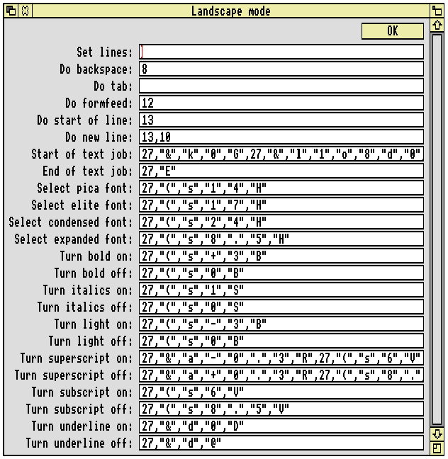
Set lines and Do tab are unused, Do backspace and Do formfeed are obvious, and all of the other strings except Start of text job are as for dp class printers above.
The Start of text job string has seriously overflowed the icon in the window; use PrintEdit on the DeskJet+ file to see all of it. There is much that is assumed about this string.
At the start of a text job, the lj back-end resets the printer with Esc E, as per Hewlett- Packard guidelines. Next it sends the paper feed (auto or manual) selection sequence and paper size settings from the Messages file, in the same manner as the setting of PDumperLJ$Extra described earlier. Then the actual Start of text job string is output, and finally the number of lines per page is set with an Esc &lxxF sequence. Thus the position of the Start of text job string is fixed, and there are HP guidelines which specify the order in which various things must be set to ensure that the printer chooses the closest match it can manage. The fixed position may impose some limitations on what you can put in the string. As well as getting the order of everything correct, the string must select landscape or portrait orientation as appropriate. It must also define the settings for both the primary and secondary printer fonts: the secondary font is used for page titles (if enabled), and the primary font is used for everything else.
The superscript and subscript strings deserve mentioning. There are no such effects on LaserJet compatible printers. The Turn subscript on string merely reduces the height of the text. The Turn superscript on string moves the baseline of the text up, and reduces the height of the text. Quite a few printers do not perform these actions well.
There is actually a control sequence for requesting light printing on LaserJets (used above), but very few printers are capable of doing it. This feature is only really present because it is in the 1st Word Plus file format.
Editing Character mappings allows a character from the Acorn character set currently in use to be converted to the same character in the printer's character set. For example on UK systems the mappings provided are for Acorn Extended Latin1, whereas for a Turkish system a new set of printer definition files would have to be supplied containing Latin3 character mappings.
Part of the character mappings for the Epson.EX-800 file are show below:
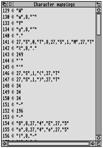
These mappings are used to convert from the Acorn character set in use to the printer character set. For example to print character 130 (' ' - w circumflex) a 'w' is printed, then the print head is backspaced, and then a '^' (circumflex) is printed on top of the 'w'.
The character mappings in a given printer definition file are specific to a certain RISC OS alphabet. For instance, the character mappings in the files supplied with RISC OS 3 (version 3.10) are all for Acorn Extended Latin1 since that is the correct alphabet for the UK territory. A localised system would come with a new set of printer definition files containing mappings for the correct alphabet (eg. Latin3 for a Turkish system). All characters from 32 to 255 can have mappings, even though none of the supplied files have mappings for characters less than 128. If there is no mapping, the character is sent straight through to the printer unaltered. The USA character set is selected for Epson compatible printers in the Start of text job string because the USA printer character set matches exactly characters 32 to 126 in Acorn Extended Latin1.
A mapping should take up only one character position on the paper. For example character 154 ('?' - OE diphthong) might reasonably be mapped as an 'O' and an 'E' next to each other ie. 'OE'. However, this takes up two character spacings on the paper, which is not allowed. This is because the Printers application's and the back end's idea of where the output had got to would not match what was on the paper. Also 1st Word Plus (and hence 1st Word Plus fancy text files) assumes that all characters only take one character spacing on the paper. Finally, with the example given above you can't tell from the paper copy whether the file has an '?' diphthong in it or an 'OE' pair, hence it is not an accurate representation of the file. An 'O' and an 'E' printed on top of each other doesn't look very good (although on the EX-800 the 'E' is italic which improves matters) but at least it is unique and distinguishable from all other characters.
Earlier we mentioned that text highlights sometime clash with each other. They also clash with some of the character mappings. For example character 141 ('?' - the trademark symbol) is obtained by printing a superscript 'T' and a subscript 'M' on top of each other. This disables subscript (and superscript) at the end of the sequence. So if superscript or subscript is in effect when the '?' character is printed, they will be switched off on the printer afterwards even though they should still be turned on. The italic 'E' in the '?' example used earlier would cause the same problem with italics. If these clashes are a problem for you, then you can change the character mappings to try to avoid them. As a result some of your mappings will not be as good, and you need to decide what compromise to arrive at.
You must map every character in the Acorn character set in use, regardless of how poor a mapping you can provide. The Printers.Generic.Text file maps each top bit set Acorn Extended Latin1 character to a single top bit clear character, for use with line printers and other extremely primitive print mechanisms. Use the mappings in this file as the absolute minimum representations.
The printer definition files supplied with RISC OS 3 (version 3.10) contain three main groups of character mappings for dp printers. These groups are based on what character sets in the printer are used. All files make use of styles and backspace over-printing where possible to supplement these printer character sets.
The first and simplest is the 'FX-80' group (see the Epson.FX-80 file). This uses the basic top bit clear USA character set, and some switches to other countries' character sets for extra characters. The USA character set is selected in the Start of text job sequence (ESC, 'R', 0).
The second is the 'ESC t 1' or 'Code Page 437' group (see the Epson.EX-800 file). This uses the basic top bit clear USA character set, the Epson Character Graphics top bit set characters (the same as IBM Code Page 437), and some switches to other countries' character sets - though less so than in the 'FX-80' group. The USA character set (ESC, 'R', 0) and the Epson Character Graphics set (ESC, 't', 1 ESC, '6') are selected in the Start of text job sequence.
The third and best is the 'Code Page 850' group (see the IBM.Pro-X24E file). This uses the IBM Code Page 850 character set, which has a perfect single character mapping for all characters except the Acorn extensions to Latin1 between characters 128 and 159. Code Page 850 (Esc, '[', 'T', 4, 0, 0, 0, 3, 'R' Esc, '6') is selected in the Start of text job sequence. Also, if the printer is not already in IBM emulation mode this should be selected; for example this is done in the Citizen.Swift-24 file.
Obviously there are deviations within each group, and there are in fact too many to go into here. However, it is useful to recognise what the major groupings are, pick one, and then tweak it to fit your printer. There are also some files that are not in any of the groupings; for example the Generic.Text and Star.DP-510 mappings.
The character mappings for the Integrex differ from the classes given above. You can view them from PrintEdit; there are no unusual features worthy of mention here.
The character mappings for the ImageWriter differ from the classes given above. You can view them from PrintEdit; there are no unusual features worthy of mention here.
The complete character mappings for the DeskJet+ file are:
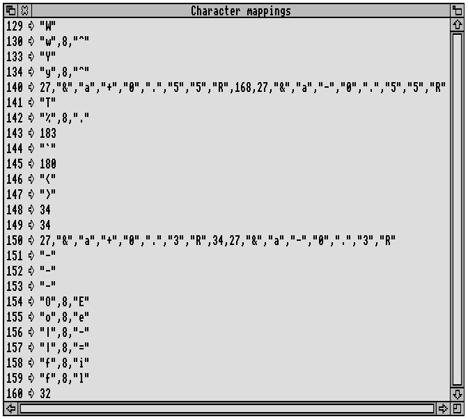
Only the Acorn extensions to Latin1 (characters 128 to 159) need to be mapped, because the 'Start of text job' string selects the ECMA-94 character set, which is the same as ISO Latin1. Character mappings 140 and 150 are of interest. Character 140 ('...' - the ellipsis symbol) is obtained by moving the text baseline down and printing the '¨' (diaeresis) character, and then, of course, moving the baseline back. This gives two dots at the right height, which is better than one, although there should be three. Similarly character 150 ',' (bottom double quote) is obtained by moving the baseline down and printing a normal double quote. These two examples show that it pays to be imaginative when dealing with a flexible printer like a LaserJet compatible. Such tricks are impossible on a dot matrix printer.