
|
www.riscos.com Technical Support: |
The ARM architecture changed significantly with the introduction of the ARM6 series. The section below describes the differences in behaviour of more recent ARM processors, used with RISC OS 3.5 and later. For details of earlier ARM processors, see the chapter entitled ARM Hardware.
The most notable change made in the ARM6 series was to extend the address bus and program counter to a full 32 bits. As a result:
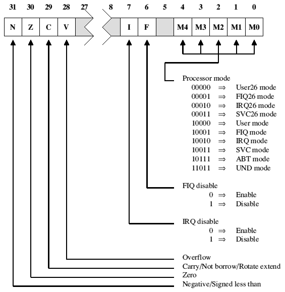
A further change was the addition of extra privileged processor modes, allowed by the PSR now having a full 32 bits to use. These modes are used to handle Undefined instruction and Abort exceptions. Consequently:
The availability of these features in the ARM6 series (and other later compatible chips) is set by one of several on-chip control registers. One of three processor configurations can be selected:
When configured for a 32 bit program and data space, the ARM6 and ARM7 series support ten overlapping processor modes of operation:
The distinction between processor modes and configurations is important, and will be rigidly adhered to in the rest of this manual.
When in a 26 bit processor mode, the programmer's model reverts to that of earlier 26 bit ARM processors. The behaviour is the same as that of the ARM2aS macrocell with the following alterations:
In all other respects, when operating in a 26 bit mode the ARM behaves as like a 26 bit ARM. (See the chapter entitled ARM Hardware.) The relevant bits of the CPSR appear to be incorporated back into R15 to form the PC/PSR with the I and F bits in bits 27 and 26. The instruction set behaves like that of the ARM2aS macrocell, with the addition of the MRS and MSR instructions.
Early in its startup code, RISC OS writes to the ARM's control register to change it into the 32 bit program and data space configuration, where it remains. You must not alter the processor's configuration yourself when writing code for RISC OS.
Although RISC OS runs under a 32 bit configuration, it remains in 26 bit modes for normal operation, providing a high degree of backward compatibility with code written to run on earlier 26 bit processors.
However, because the processor is in a 32 bit configuration, all exceptions (including Undefined Instruction and Software Interrupt) force the processor to a privileged 32 bit mode appropriate to the exception. There are therefore some differences in exception handling between 26 and 32 bit architecture ARM chips, although RISC OS provides a considerable degree of backward compatibility by faking 26 bit behaviour on 32 bit architecture chips in most circumstances. For full details, see the chapter entitled Hardware vectors.
The registers available in the ARM6 and ARM7 series are:
| User and User26 mode | SVC and SVC26 mode | IRQ and IRQ26 mode | ABT mode | UND mode | FIQ and FIQ26 mode |
|---|---|---|---|---|---|
| R0 | |||||
| R1 | |||||
| R2 | |||||
| R3 | |||||
| R4 | |||||
| R5 | |||||
| R6 | |||||
| R7 | |||||
| R8 | R8_fiq | ||||
| R9 | R9_fiq | ||||
| R10 | R10_fiq | ||||
| R11 | R11_fiq | ||||
| R12 | R12_fiq | ||||
| R13 | R13_svc | R13_irq | R13_abt | R13_und | R13_fiq |
| R14 | R14_svc | R14_irq | R14_abt | R14_und | R14_fiq |
| R15 (PC) | |||||
| CPSR | |||||
| SPSR_svc | SPSR_irq | SPSR_abt | SPSR_und | SPSR_fiq | |
32 bit register organisation
These are similar to those available in the ARM2 and ARM3 series registers. The key differences are:
The allocation of the bits within the CPSR (and the SPSR registers to which it is saved) is shown below.
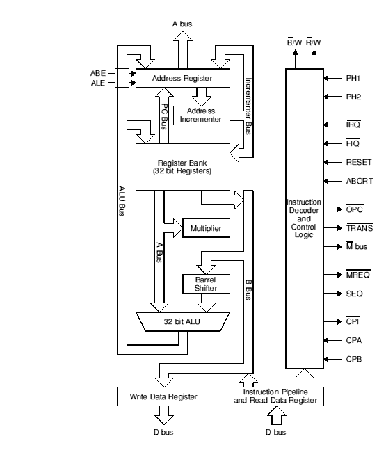
ARM Core block diagram